3D Felting Machine
The surface of wool fibers is covered with tiny scales (the cuticle layer). When the fibers are rubbed or pierced, these scales catch onto one another. Felting needles have small barbs along the shaft that push loose fibers into the core with each poke. As the fibers become more entangled, the gaps between them shrink, making the material tighter and firmer. Repeated needle felting gradually transforms loose wool into a compact and stable form. Because the shrinkage behavior of natural wool fibers is non-linear, identical needling counts, depths, and frequencies can result in different degrees of tightening and contraction at different stages of the process.
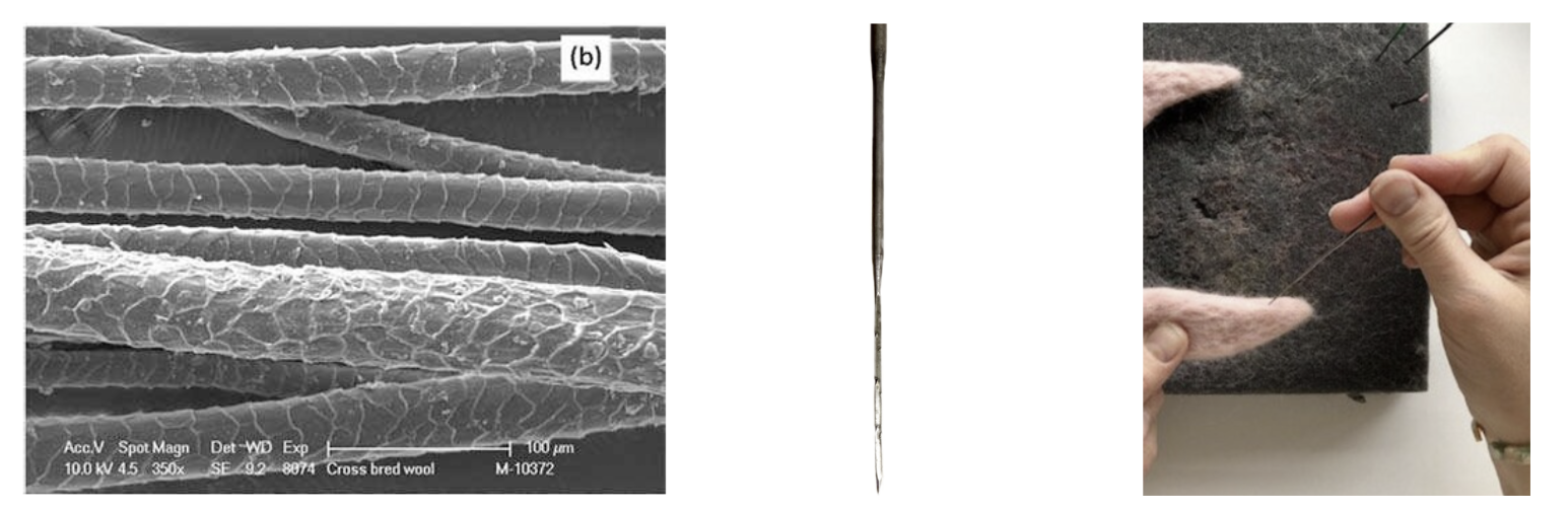
Figure 1. a. Wool fibers with microscopic surface scales. b. Felting needle with barbs. c. Manual needle-felting process that compresses fibers into a dense form.
Prior Work
has explored the use of robotic-arm needling and the intrinsic properties of wool felt to generate a variety of 2D felted surface textures. These textured sheets have further been folded, in an origami-like manner, to produce 2.5D geometries. A project from CMU used a form similar to a sewing machine to fabricate wool felt, extruding the material as a yarn and creating surfaces with a striped appearance.
Previous research has mainly focused on designing a sequential system, using predefined needling setups or chemical methods to produce wool felt. These approaches effectively turn wool felt production into a linear system. My aim is to explore how we can compute within a non-linear system by mimicking the way humans create wool felt.
System Design
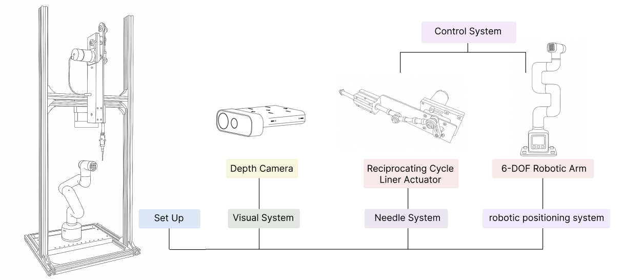
Figure 2. System set up
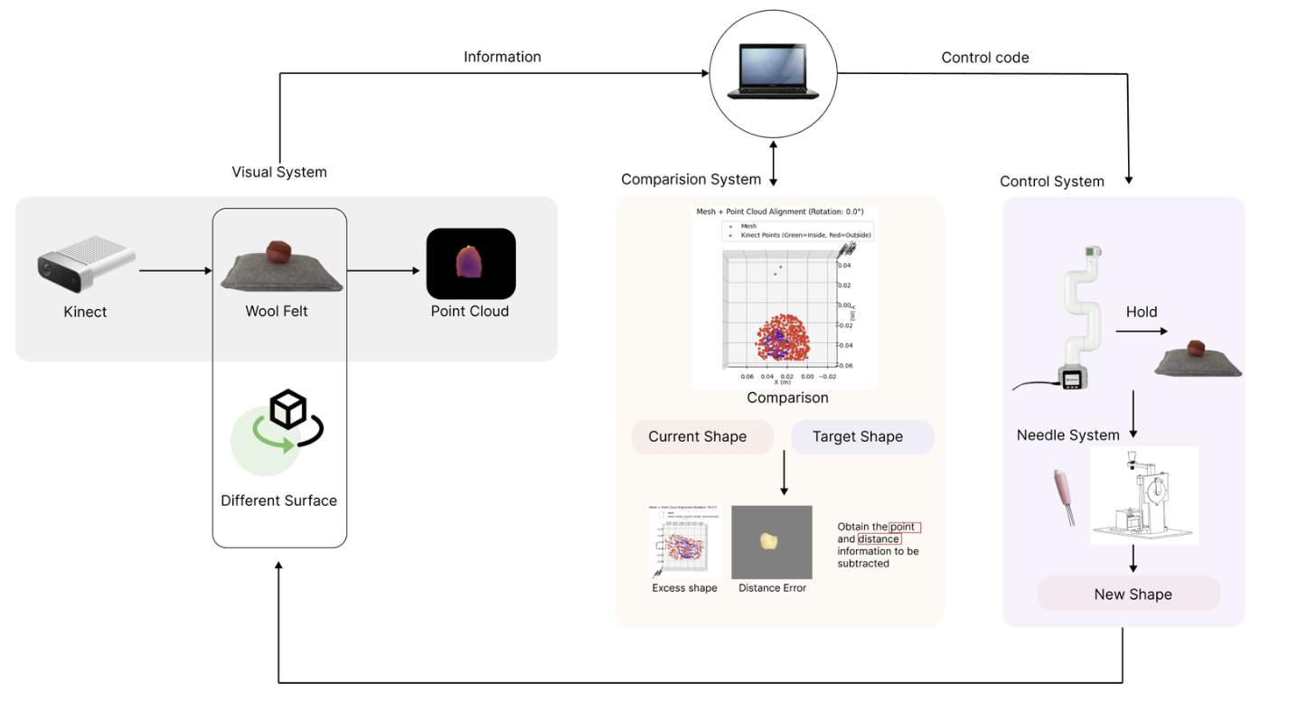
Figure 3. System Diagram
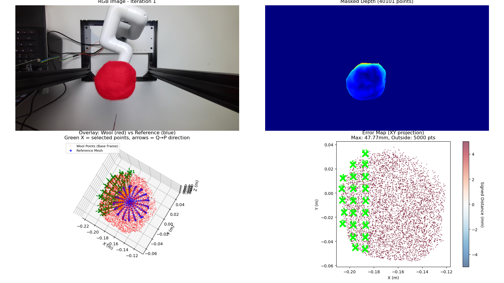
Figure 4. Comparison System
System Validation
The video demonstration shows the system randomly selecting ten points and moving the robotic positioning system beneath the needle system to process each point.
Experiment - Convex Shape
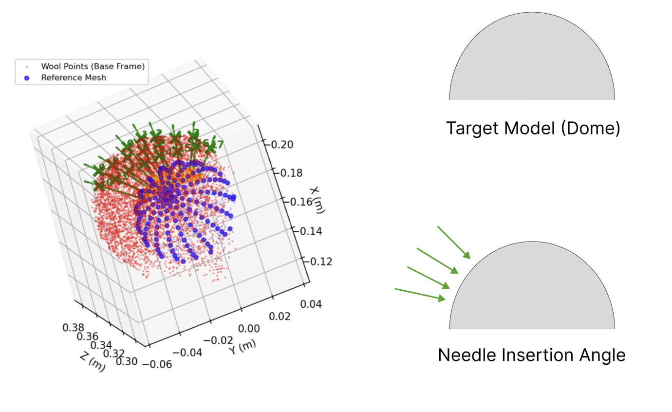
The system adjusts the needle insertion angle according to the surface normal of the target model, ensuring that each processed point is oriented at 90 degrees to the needle. In each round, the system proceeds through five views in the order of top, left, right, front, and back, processing one surface at a time. Each surface is further divided into left, center, and right regions, and a generated grid within each region is processed sequentially.
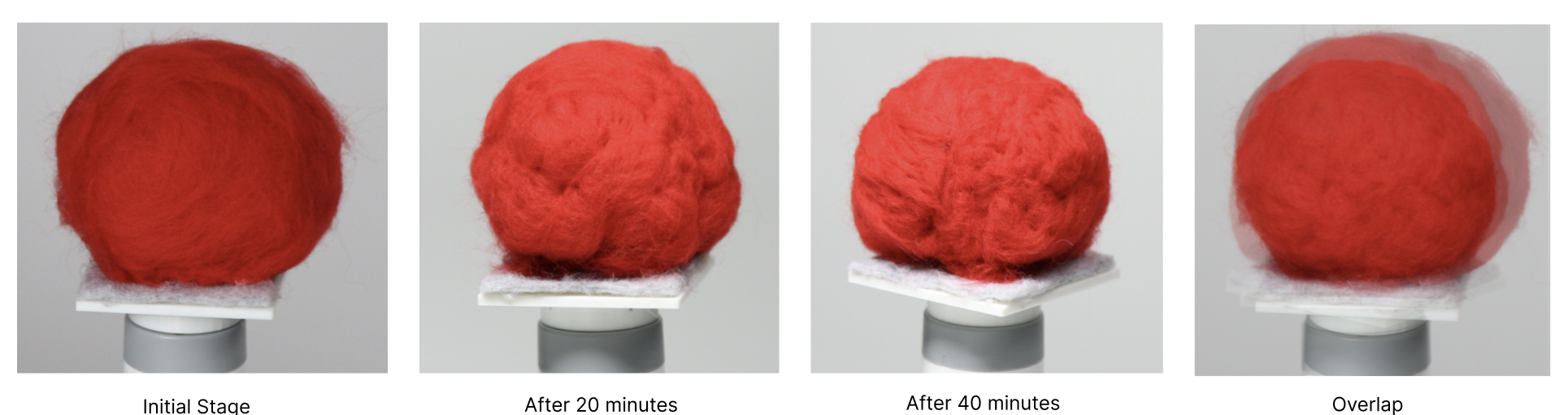
Figure 5. Test results
This video demonstrates the fully automated workflow of the entire system.
Experiment - Hard Shell
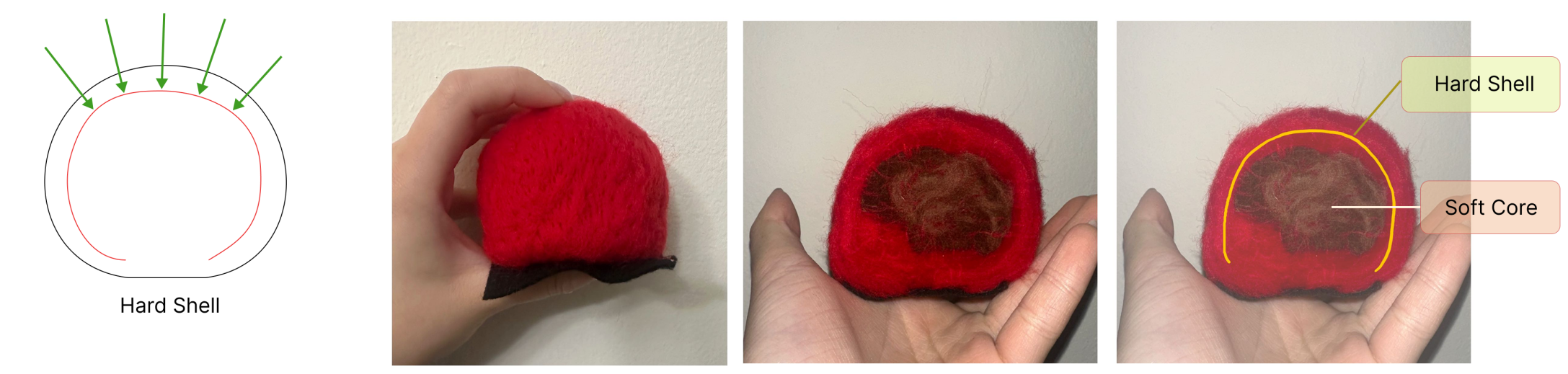
This experiment investigates how robotic needle felting can be used to construct a hardened outer shell while preserving a softer internal volume, exploring the material behavior of wool felt as a nonlinear, compressible medium.
Unlike traditional additive fabrication processes that build structures layer by layer, this approach operates on an existing fiber mass and selectively compacts regions through controlled needle insertions. By modulating insertion depth and spatial distributio, the system is able to densify the outer surface while limiting deformation in deeper regions.
The result is a shell-like structure with a relatively rigid exterior and a compliant interior, a configuration that is difficult to achieve consistently through manual felting.